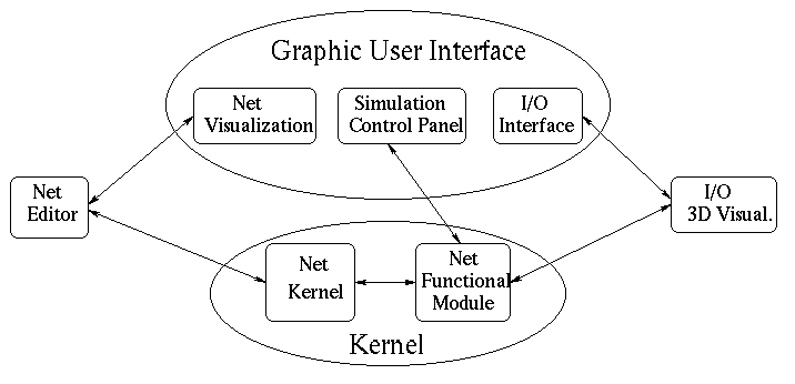
Figure 1: INNE architecture
The structure of the application is displayed in Fig. 1 and consists of the Kernel module, the Net Editor, the 3D Visualization tool and the GUI module.
The GUI module includes the Net Visualization tool, a graphical window
that interacts with the net editor
and allows the definition of the network architecture and of
its layout.
The Net Editor provides tools for managing a subset of nodes and/or
arcs as an object to ease the job and allowing the definition of large nets.
Moreover, users attach a behaviour to the network they are editing through the
GUI module acting on a Simulation Control Panel and choosing among
one of the predefined models.
The 3D Visualization module helps to understand the processes that occur during the learning
phase and, in other cases, to visualize the results of the computation.
The Kernel module is subdivided into two parts: the former to manage the network
with its nodes and arcs,
the latter to compute the behaviour according to a model.
While the interface is written using the X11-R5 libraries and Motif 1.2 the kernel is written in plain C language for portability reasons. The 3D Visualization module, also written adopting Motif libraries, is a tool implemented in the CoLoS project.