Via Comelico 39/41 - 20135
e-mail: author-lastname@dsi.unimi.it
Milano, Italy
Contents:
I. THE GEOMETRIC MODELLING PROBLEM
We have developed an object-oriented environment, GEObject, aiming at providing
a geometric modelling tool, based on compass-and-ruler constructions
[Alberti95a] [Alberti95b]. A geometric construction indeed can be seen as a
series of successive operations, consisting of instantiation of geometric
entities (e.g. lines, circles etc.), generation of new points, as intersection
of these entities, which will be used to create new entities with simple
constructive methods until the desired result is reached. The user interface
enables users to interact with the figure and the entities that constitute it,
enabling plane transformations and maintaining relationships among objects,
that is the geometric constraints.
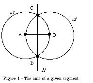
As an example of a compass-and-ruler construction, let us now define the axis of a given segment. One could draw the segment, giving its end-points, and then two circles respectively centred in each end-point and radius equal to the segment itself. The axis of the segment will be the line passing through the intersections between the two circles (see Figure 1). In the process one specifies by construction some constraints among the entities involved in the figure: in the example, the line CD is orthogonal to segment AB.
We are now interested in applying transformations to the figure as a whole or to any of its sub-parts that will have to preserve the internal relationships among entities in the figure. In other words we are to solve a problem of constraint maintenance during transformations. Our approach provides a simple method to declare the constraints that bind the elements during the construction and to solve the constraints during transformations, without recurring to numerical solution methods [Borning79].
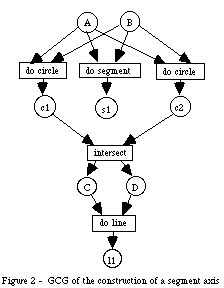
GCG's nodes are interpreted as geometric objects, represented by circles, or as constructive methods named actions, represented by rectangles. Arrows indicate objects required as parameters of an action and its outputs, the generated objects. Arrows establish a partial temporal order among the operations that will lead to the figure. In Figure 2 we show the GCG describing the construction of a segment axis. The complete semantic of GCG is given in [Evi94].
The system maintains an internal representation of the GCG and turns to it for constraint solving during transformations. Moreover, GCGs are helpful in describing informally and in an intuitive way a problem which has intrinsic concurrent aspects. We observe, for instance, that in Figure 2 do_circle and do_segment actions are independent from each other and the order of execution is not relevant, they can be executed simultaneously or in whatever order. This independence produces concurrency (actions can be executed simultaneously) and non-determinism (execution order is not pre-defined).
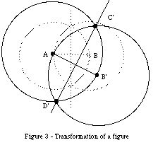
While during the construction process users actually perform actions sequentially, concurrency can be exploited by the system, when it responds to the users' action of transforming the figure. More precisely, users can translate one of the points involved in the figure and the system reacts by re-traversing concurrently the graph that describes the construction. For example, in the simple case of translation of a primitive point, as in Figure 1 where point B is moved in B', the whole figure must be drawn again, as shown in Figure 3. In order to achieve the desired result the system has to repeat the operations specified in Figure 2 by the GCG, starting from the primitive objects, represented by the nodes labelled A and B, following the arcs and executing the specified actions do_segment, do_circle, intersect, do_line. The two actions do_circle, and do_segment can be executed concurrently. The action intersect can be executed only after the two do_circle actions, and the action do_line after the intersect one. Indeed, each action produces new objects that will in turn trigger other actions until the whole figure is transformed.
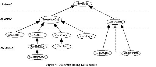
At the first level of abstraction, each geometric object can be seen as an instance of the class GeoNode. This class characterises a generic geometric object defining his name and a set of deferred interaction methods (i.e. to apply geometric transformations, to modify the graphic aspect, etc.). Instances of the GeoNode class correspond to nodes in the GCG represented by circles.
At the second level of abstraction, we have to distinguish between entities with a geometric nature (GeometricObject) and those with a numeric nature (GeoViewer). The first ones have associated some geometric methods, as for example intersect. The last ones are used to visualise numeric attributes of the geometric objects (i.e. segment length, angle width, etc.) and to compute further numeric values related to the figure. In fact, these objects have associated some algebraic methods like +, -, *, /, sqr, ...
At the third level of abstraction, we have to distinguish among different geometric entities (points, lines, circles, ...) and different numeric objects. At this level we supply the implementation of each deferred interaction methods (as intersect, geometric transformation, ...) and of the specific creation methods, which enable users to instantiate objects in different ways (as a circle given its centre and one point or a circle given three points).
For example let us suppose we want to define the new class of equilateral triangles; we will have to construct an equilateral triangle starting from two vertexes so that the system can "learn" the construction generating automatically the Eiffel code corresponding to the new class GeoEquiTriangle. From now on users can draw a generic equilateral triangle without repeating the whole construction but simply sending the creation method of the new class.
In the same way the segment-axis construction can be added to the system as a new interaction method of class GeoSegment or new creation method of a new class, say GeoOrthoLine. Indeed, it is users' choice to decide what is appropriate in terms of the geometry taxonomy they have in mind.
Among different types of Petri Nets we chose OBJSA nets for the following reasons:
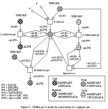
The construction of a segment axis can be modelled by the OBJSA Net, see Figure 5. In the net there are four OBJSA components, one for each geometric entity: Point, Line, Segment and Circle. Tokens of each such component are structured in a name part (NAMEPART) and a data part (POINTDATA, LINEDATA ...) holding the specific data. Each action in the GCG has been modelled by a transition obtained by super-position of the open transitions of the involved components.
The open transition P-with-x-y models the action to instantiate a point by its co-ordinates. This transition has no correspondence in GCG.
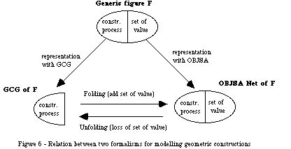
The two formalisms, GCG and OBJSA Nets, to represent a geometric construction, briefly sketched above, are strongly related; in fact if we unfold the OBJSA model, which represents the construction process of a figure, we get a GCG. The unfolding process that we apply to the OBJSA models is only a partial one. In fact a geometric figure can be seen as a couple: a construction process and a set of values to be associated to the geometric instances. The GCG model captures the construction process whereas the OBJSA model captures also the numeric value of geometric instances (i.e. points co-ordinates). The unfolding process from OBJSA to GCG involves loss of information whereas the reverse process requires addition of information. In Figure 6 we show this concept. On the other hand GCG represents a construction in a more abstract way, i.e. it represents the class of all figures produced by that construction.
Without getting into details, when an object receives a transformation message, it backwards it to the objects that had generated it (i.e. a segment sends the message to its end-points). This process proceeds until the message arrives to the primitive objects of the construction. The primitive objects change their position according to the transformation message and forward it to their descendants and then on to the descendants of the descendants, until the message gets to terminal objects in the figure. If the transformation is compatible with the geometric constraints of the figure, then some or all objects in the figure will have a new position.
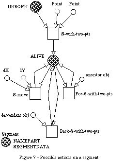
In our work we have modelled with OBJSA the transformation process, too. As an example, we give the OBJSA complete net of a segment generation and further transformations, see Figure 7. In this figure, we see that after a segment is created by means of the S-with-two-pts transition (the token is moved from the UNBORN place to the ALIVE one), it can be transformed by users (this action is modelled by the S-move transition) or it can receive a backward message by its possible descendants (this action is modelled by Back-S-two-pts transition) or a forward message by one of its end-points (modelled by For-S-with-two-pts transition). For a complete description, we refer to [Evi94].
Both the construction and the transformation process modelled by means of OBJSA Nets have been simulated in the environment ONE [Battiston88], allowing us to verify correctness and termination properties of algorithms.
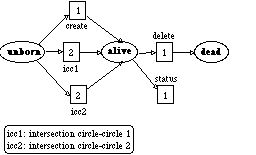
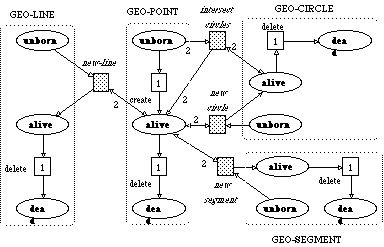
The GEO-POINT class has a set of creation methods: create to generate a new point at the (x, y) co-ordinates, icc to generate a couple of new points as intersection between two circles (due to the implementation, methods return only one value, so icc is actually split into icc1 and icc2 to return the first and the second intersection point). The GEO-POINT class has a set of interaction methods, we report only delete to remove the point, according to users' request and status to allow inquiry about the point co-ordinates by the system when new objects are being instantiated starting from the point itself.
class GEO-POINT
inherits
(*) GEO and USER are special classes that model the generic geometric class and the user, respectively.
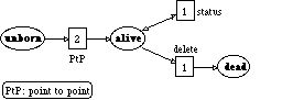
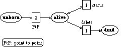
Moreover, for each CLOWN class a net is defined that describes the behaviour of its instances during their life cycle, from the unborn status to the dead one, through the alive one.
net GEO-POINT
The GEO-SEGMENT class inherits from the GEO-LINE one and redefines its PtP creation method, to instantiate a line from two given points, and introduces a new interaction method called size to measure the segment length.
class GEO-LINE
inherits
net GEO-LINE
class GEO-SEGMENT
inherits
(*) ERAT stands for Extended RATional and defines the type to deal with rational numbers allowing also the square root operation.
net GEO-SEGMENT
Finally, the compound class SEGMENT-AXIS defines the complete process of construction of a segment axis in the CLOWN formalism. Users can obtained it by composing pre-defined elementary CLOWN classes.
compound class SEGMENT-AXIS
The following net, associated to any compound class, shows the life cycle of the CLOWN objects. As a future development in CLOWN, this net will be derived automatically starting from the elementary classes GEO-POINT, GEO-LINE, GEO-SEGMENT and GEO-CIRCLE.
According to CLOWN semantics [Chizzoni94] one can derive the OBJSA net in Figure 5, modelling the same segment-axis construction. The two nets are indeed equivalent, except for the dead place, which is required in CLOWN.
The compound class in CLOWN formalises the possibility, offered by GEObject, of extending with new constructions the geometric classes and methods. For instance, the user defined class GeoEquiTriangle given previously as an example of GEObejct incremental features, is formalised in CLOWN by a compound class. But also the segment-axis construction, seen as a new interaction method of the class GeoSegment, is formalised as a compound class.

We have seen a simple and intuitive formalism, the GCG, to describe step by step the construction of a geometric figure. However the GCG semantics is not well defined. So we have adopted the OBJSA Net: they guarantee uniqueness of interpretation of the model. Despite the OBJSA Net are suitable to represent an object-oriented environment, they don't support users in translating their object-oriented models into OBJSA models. CLOWN supplies an object-oriented like language, with which it has been possible to establish a correspondence between classes/methods in Eiffel and classes/methods in CLOWN, keeping the same class hierarchy. Moreover, CLOWN has proven to be an effective language to formalise the incremental character of GEObject by means of the compound construct.